
Why parallel work helps—sometimes
Compare one worker with a group of workers. This toy model uses equal-cost jobs and abstract time units. CPUs also have multiple cores and vector units; these are not real CPU/GPU performance measurements.
QUANTUM SHARMA · SILICON ATLAS
Open a branch, inspect a device, and connect what you learn to something you can build. Understand CPUs, GPUs, RAM, SSDs and solar cells through one visual learning map.
Try three working models → Start with the foundations →
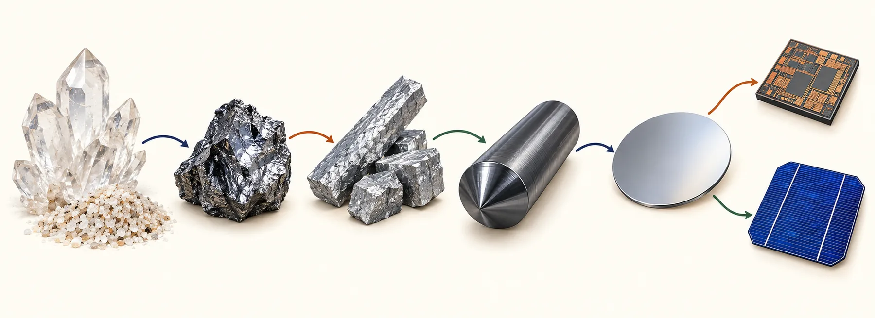
One starting material, many structures. Products also use metals, insulators, packaging and other materials. The tree follows learning relationships; real systems combine several branches.
Silica is silicon combined with oxygen. Quartz-rich feedstock is selected and processed; a handful of ordinary sand is not ready-made chip material.
Explore the deeper guide →Industrial reduction changes silica into silicon. This changes the chemistry; the resulting material still needs further purification for demanding electronic uses.
Explore the deeper guide →Chemical processing removes unwanted impurities and produces high-purity polysilicon. Controlled doping later adds selected impurities for a purpose; it is not the same as leaving contamination behind.
Explore the deeper guide →A controlled crystal-growth process creates an ingot with an ordered atomic structure. Purity and crystal structure are separate properties.
Explore the deeper guide →An ingot is sliced and its surfaces prepared. A wafer is a starting surface for device processing, not a complete CPU or solar cell.
Explore the deeper guide →Different processes form active regions, insulating layers and connections. Chip making repeats many tightly controlled steps before testing, separation and packaging.
Explore the deeper guide →A CPU executes instructions using control logic, registers and arithmetic units. Caches and memory connections help supply its work. Modern CPUs also exploit parallelism.
Explore the deeper guide →Follow an instruction through fetching, decoding and execution. Register values and arithmetic results are different from data stored in an SSD.
Explore the deeper guide →A cache keeps selected data close to computation. A memory controller connects the processor to external memory; a larger cache is not the same thing as a larger SSD.
Explore the deeper guide →A GPU organizes many arithmetic workers, schedulers, registers, caches and memory connections. Parallel work helps only when the algorithm and data movement permit it.
Explore the deeper guide →See how groups of threads use execution lanes and shared resources. A GPU arithmetic lane and a complete CPU core are different units, so their counts are not a direct comparison.
Explore the deeper guide →VRAM is memory attached to a GPU. Capacity, bandwidth and latency describe different limits. Adding memory needs a supported electrical, board and software configuration.
Explore the deeper guide →GB202 is a GPU design used in both the RTX 5090 and RTX PRO 6000 Blackwell. The products have different enabled configurations and memory systems. Explore what is physical and what is a product choice.
Explore the deeper guide →Two GPU boards have separate local memories. Splitting data or a model across devices needs compatible communication paths and software; it does not turn them into one equally fast memory bank.
Explore the deeper guide →The same broad semiconductor material can form different ways to hold a bit. SRAM, DRAM and NAND flash trade area, speed, persistence and other properties differently.
Explore the deeper guide →An SRAM cell uses a feedback circuit to hold a state while powered. It needs no periodic DRAM-style refresh, but it is still volatile.
Explore the deeper guide →A DRAM cell represents a bit using stored charge. Charge leaks, so refresh is required. A RAM module combines memory devices and supporting connections.
Explore the deeper guide →Flash stores information through charge that changes a cell’s electrical behavior. 3D NAND stacks cell structures; it is different from stacking ordinary RAM sticks.
Explore the deeper guide →An SSD combines NAND flash with a controller, firmware and interfaces on a board. It is an assembled storage system, not one uniform silicon chip.
Explore the deeper guide →The controller maps logical addresses, manages errors and moves or retires physical flash blocks. NVMe describes a host interface, not a type of flash cell.
Explore the deeper guide →A crystalline-silicon solar cell uses light to generate electrical energy. It branches into a different device process rather than following the complete CPU fabrication route. Other photovoltaic materials also exist.
Explore the deeper guide →Absorbed light can create mobile charge carriers. The cell structure and contacts collect them; a connected load lets electrical energy be delivered to a circuit.
Explore the deeper guide →Connected cells form a module with protective layers and wiring. Series and parallel connections affect voltage and current; shading and cell mismatch complicate real systems.
Explore the deeper guide →Build a small Boolean circuit now, check every input and export Verilog. Then learn what synthesis, physical design and a process design kit add to the evidence.
Explore the deeper guide →Start with particles, charge and current. Track what moves through a wire and distinguish electron motion from the direction of conventional current.
Explore the deeper guide →A gate voltage can control a transistor’s conducting path. Combine complementary switches to understand an ideal CMOS inverter, then inspect where the simple switch model stops being enough.
Explore the deeper guide →Use powers of two to represent an unsigned number. Add two eight-bit values and follow the carry when the result exceeds the available bits.
Explore the deeper guide →A tiny teaching machine fetches, decodes and executes instructions. Step through a calculation and watch the program counter, accumulator and memory change.
Explore the deeper guide →Compare one worker with a group of workers. This toy model uses equal-cost jobs and abstract time units. CPUs also have multiple cores and vector units; these are not real CPU/GPU performance measurements.
Write the same pattern into idealized DRAM and NAND, then switch power off and on. This compares volatility after a completed write. Real SSD recovery, endurance and interrupted writes need additional mechanisms.
Power on. Try writing a pattern.
Choose a starting point or follow these four guides in order. Each includes an original diagram, a worked example and questions with answers.
Connect moving charge to a measurable current, with a worked calculation.
Learn more →See how complementary transistors make an inverter and where the ideal model has limits.
Learn more →Read an eight-bit number, add values and explain a carry beyond the last bit.
Learn more →Follow a small calculation through instructions, registers and memory.
Learn more →Start with a switch, then build gates and verify a half adder. Keep the circuit, expected results and exported design together. The making guide shows the next industrial stages without claiming a simulated circuit is a finished chip.
Electricity lessons → Build logic online → How devices are made →